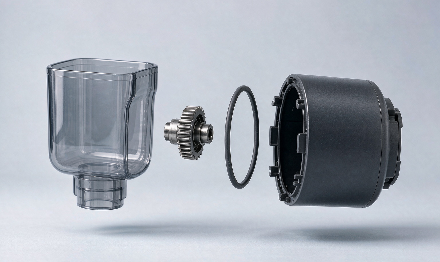
The prototype to mass production gap is the distance between a design that satisfies every geometric check and a design a factory can actually assemble, repeatably, at volume. That distance is where most hardware launches quietly die — and it is almost never about material choice or tolerance stack-up. It is about sequence: whether a human holding a part in two hands can physically install it, in that order, without a fixture nobody wrote down.
The Launch That Died at 11 Weeks to Go
Marcus' smart pet feeder had the most beautiful prototype we saw that year. Softened fillets, a smoked translucent hopper, an app that worked. He raised a $2.4M round on it. His board had already printed the production schedule — first shipment to Amazon in 14 weeks.
Then his contract manufacturer started playing assembly sequence videos.
The hopper had to be filled with kibble after the drive collar was mounted. The collar could not be mounted until the fill port gasket was seated. The gasket could not be seated because the port's snap-fit hooks were blocked by the collar's flange — and the flange could not clear the port because the collar's retaining ears sat 0.4 mm inside the housing wall.
Every individual part was correct. Every part fit. The CAD assembly looked clean. And the assembly was impossible in that sequence, which is not the same as impossible.
Marcus went quiet for a week. Then he asked us the question that has since framed our whole practice: "How did we get here with a model that checks out?"
Look, we get it. You spent nine months on that design. So did we. Nobody is bad at their job here — the failure is structural, not personal.
At SciPure Tech (溯朴科技) in Shenzhen, our founder came out of the Foxconn-Apple joint lab — roughly two decades of carrying consumer-electronics and home products from whiteboard to tens of millions of identical units. We hold 29 granted patents, and our founder was named a Shenzhen science-and-technology leadership talent in 2020. We are a Shenzhen-based product engineering advisor that helps consumer-electronics and home brands manage the full journey from concept design to mass production — DFM optimization, injection molding, electronics assembly, QC systems, and supply chain development. That work runs on our own 2,000 m² production facility in Shenzhen's Guangming District (海鑫光高科技工业园), ISO 9001 certified, with IQC/IPQC/FQC/OQC full-process inspection and an AQL 1.0 outgoing standard. We have capacity; what we sell is engineering judgment. A client can build on our lines or take the design package back to their own factory — the engagement holds either way.
Marcus had a manufacturable product and an unmanufacturable assembly order. That distinction is the whole topic.
The Gap Is a Space Problem, Not a Material Problem
Here's the part that stings: if your prototype-to-production failure is going to be expensive, it's almost always a spatial-sequence failure — and it surfaces after tooling, not before it.
Here is why this is changing. For twenty years, DFM review meant checking one thing: does this geometry produce a valid part? Draft angles, wall thickness, ribs, radii, shrink, parting line. That question is now largely answered by software in minutes.
What software still struggles with — and what tooling does not catch at all — is whether the assembly can be executed as a physical sequence of motions by a human or a two-axis robot. Every industry making AI tools right now is attacking precisely this gap:
- Hestus raised a $7.4M seed (Oct 2026, total funding $8.9M) to build a model that translates engineering intent into manufacturable design, already used by 5,000+ engineers inside Autodesk Fusion, with a SolidWorks alpha underway.
- C-Infinity's AutoAssembler reasons over interference, accessibility, motion paths, sequencing, and stability — explicitly the failure class Marcus hit — and reframes DFMA as something that "can increasingly happen continuously throughout product development" rather than at a checkpoint.
- Limitless Labs at IMTS 2026 argued the same thesis for machining: the binding constraint has moved from machine capacity to the program, and their CAM agent now handles CNC/CMM/DFM end-to-end inside Siemens NX and Mastercam.
- Trace.Space (Trinity, Oct 2026) is attacking the neighboring wall — requirements, test, and variant traceability across prototype generations, already used with Lucid Motors and Serve Robotics.
Every one of these companies is selling the same insight we learned the hard way on Marcus' feeder: geometry checking is cheap and nearly solved; sequencing reasoning is expensive and unsolved. The gap is where your launch lives.
The Five Traps We Look For First
Here are the five that account for the large majority of the prototype to mass production gap we see. None of them are visible in a static screenshot of a CAD assembly.
Trap 1 — The last part installed
Every assembly has one part that must go in last. Ask: can a hand, or a two-axis robot, physically reach its final position on the last step?
- Marcus's feed collar: it had to seat after the gasket, but its path was blocked.
- A very common version: a housing that closes around a PCB with a lip thinner than the connector height. The lip has to flex past a 6 mm connector to close — so the design now depends on a controlled deformation you never validated.
- The tell: your BOM has a part whose installation requires the housing to be compliant, sprung, or thermally deformed. That is a requirement, not a detail.
Trap 2 — The captive fastener with no escape
A screw or clip that gets buried behind a fixed feature is a design defect disguised as a BOM line.
- The tell: a fastener whose axis is parallel to the removal path of an adjacent part, or which becomes physically unreachable once one neighbor is installed. On a two-zone device, this alone adds a full fixture — typically 2–5 days of tooling rework and $1,500–$6,000 in fixture engineering, plus an operator cycle the line has not budgeted.
- The fix that costs nothing: install sequence top-down and outward. If a part can only be reached from the side after its neighbor is in, rotate the neighbor, split the housing, or move the fastener to a two-shot or ultrasonic weld joint.
Trap 3 — Two features fighting for the same space
Not interference in the static sense — two features that each need clearance for a tool, a nozzle, or a gloved finger, and both claim the same corridor.
- The tell: a screw boss 9 mm from a snap-fit hook, where the driver has to swing 90° and the snap tool needs 12 mm of straight-line access. Both "fit." Neither can be assembled at that station.
- The tell, part two: a feature that requires a right-angle driver or a torque gun at an angle the fixture cannot hold. This is the single most common reason a design is DFM-clean and assembly-infeasible.
Trap 4 — Tolerance stack that only works on paper
Individual fits are drawn at nominal. Assembled, they stack — and stack grows.
- The tell: your mating parts are specified at nominal ±0.1 mm with no worst-case pass/fail documented. On a four-wall housing with a snap-fit, a 0.4 mm worst-case stack can turn an interference fit into a no-fit; on an aesthetic seam it produces a visible step that fails a premium brand's own review, not just a QC check.
- Our rule: every snap-fit needs a documented worst-case and best-case interference, computed, not assumed. If nobody on the team has written that number down, the design has not been DFM'd — it has been modeled.
Trap 5 — The process nobody owns
The part that requires a secondary operation nobody has signed off: ultrasonic welding, hot-plate reflow of an adhesive gasket, a heat-staked post, a printed conductive trace needing a cure bake, a conformal-coating mask.
- The tell: the BOM has a process step with no fixture, no cycle-time estimate, and no operator in the routing. This is the trap that pushes a launch from 4 weeks to 9 and shows up as an unexplained variance spike on Line 1 rather than as an engineering problem at all.
- The tell, part two: a material whose behavior changes with humidity or age. A rubberized grip pad that passes grip testing on day 1 and fails it at day 60 in a warehouse is not a QC problem; it is a design-material pairing problem caught by nobody.
The 90-Minute Check That Catches Almost All of It
You do not need a full DFM report to close most of this gap. You need a sequence.
A physical dry-build on the actual prototype — timed and filmed by someone who didn't design it — catches more real assembly problems in 90 minutes than a month of CAD review.
- Record assembly order on paper — no CAD, just step 1 through step N, in the sequence you believe is correct.
- Have a non-designer time it with the actual prototype and the actual hardware. We target under 45 seconds per sub-assembly; anything over 90 seconds means fixturing, not hands.
- Count the "hold" moments — every time the builder has to put the product down, flip it, or re-grip it. Three or more holds in a sub-assembly is the fixture trigger.
- Score each step for the four tells above. Any step that fails one is a red-line finding, not a note.
- Then read it against your volume. At 200 units you can absorb a 6-minute hand assembly. At 20,000 units you cannot — and that same product can be either your best margin or your worst.
That run of 90 minutes costs less than a single day of engineering and it routinely rewrites the assembly section of the drawing. If your team wants a template for how to read the output, our design for manufacturing reduce manufacturing costs breakdown walks the cost side of the same review.
What It Costs to Find This Late
Here's the range from our own project files, with the boundary condition stated: these are total rework figures for molded-and-assembled consumer electronics, not vendor quotes.
| Where you catch it | Typical rework | Schedule hit | Cost of the fix |
|---|---|---|---|
| During CAD, before CAD is released | 0–2 parts change | 0–3 days | Effectively free |
| After tooling, before first article | 1–4 parts change + fixture rework | 1–3 weeks | $3,000–$15,000 |
| After the first production run | Full re-tool or a second source | 3–8 weeks | $15,000–$60,000+ |
| After launch, at retail | Line stop, sorting, rework, expedited freight | 4–12 weeks | Brand-level |
Two things about that table are worth internalizing:
- The jump between row two and row three is roughly an order of magnitude. That is the argument for doing the review before tooling, not after. We wrote this up in cost terms in how to reduce manufacturing cost before tooling — it remains the highest-leverage hour in most hardware programs.
- Row four is a brand event, not a factory event. Suppliers get de-listed. Retail listing reviews start failing. A single bad first production run is a signal about your quality system, and buyers read it that way.
If you're already deep into tooling, the sequencing question still has leverage: it is one of the few remaining categories where you can change geometry rather than pay for a mold insert.
Where Your Timeline Actually Breaks
Most teams assume the delay comes from tooling. It doesn't, as often as they think.
When you're behind schedule, assembly-sequence fixes are the fastest recovery you have before the first production run — geometry changes are cheap, tooling changes are not.
- A geometry-level sequence fix — reorder, reorient, split the housing, add an access window — usually lands in 2–5 days including drawing release.
- A tooling-level fix — insert change, split line move, new core — lands in 3–6 weeks and typically costs $4,000–$18,000.
- A process-level fix — a new fixture or secondary operation — lands in 1–3 weeks plus line qualification.
That is why an assembly-sequence review that runs in week 4 is worth ten times one that runs in week 22. If you want the full clock, read the average timeline prototype to mass production — we mapped every phase including the 2026 certification and tariff paths that now sit on the critical path.
And yes — the process choice interacts with all of this. A part designed for 3D printing vs injection molding cost thinking will usually tolerate sequence sloppiness that a molded part cannot, because additive processes let a builder re-orient a piece instead of redesigning it. That flexibility is genuinely valuable early and genuinely dangerous past a certain volume.
The Principle
A design that cannot be assembled in a sequence a stranger can follow is not manufacturable — no matter how clean the CAD.
The corollary is the one we repeat to every founder: sequence is the cheapest defect class you will ever fix and the most expensive one you will ever buy. Ninety minutes, done before the steel exists, replaces a quarter of rework after it.
FAQ
Why can't my prototype be manufactured if the CAD model checks out?
Because CAD checks geometry, not sequence. A model can verify that every part is dimensionally valid and every feature clears its neighbors, and still describe an assembly where one part physically cannot reach its final position — because a neighbor installed earlier blocks the path, or a lip has to flex past a 6 mm connector. Sequence feasibility is a separate question from geometric validity, and it is the question that kills launches late.
How do I know if my prototype is manufacturable before paying for tooling?
Run three checks. First, a paper assembly sequence reviewed by someone who did not design the product. Second, a timed dry-build of the real prototype by a non-designer — target under 45 seconds per sub-assembly, and flag any step that forces a put-down or re-grip. Third, score every step against the four tells above: last-part access, captive fasteners, shared tool corridors, tolerance stacks with no worst-case number, and unowned secondary processes. All three fit in under two hours and cost less than a day of engineering.
What is a DFM report and what should it actually contain?
A DFM report is the written record of whether your design can be produced and assembled as drawn. It should contain: a resolved per-part feasibility assessment, a worst-case tolerance stack for every snap-fit and press fit, a fully resolved assembly sequence with cycle-time estimates, tooling and fixture recommendations, and a costed change list separated into must-do-before-tooling and can-defer. If a report only says "manufacturable, no major issues," it has not been done.
How much does fixing assembly sequence problems cost after tooling?
After tooling, expect $4,000–$18,000 and 3–6 weeks for a tooling-level fix (insert change, split-line move, new core), and $15,000–$60,000+ with 3–8 weeks if it is caught only after the first production run. Caught before the CAD is released, the same finding is normally a 2-hour drawing change with no cost. The cost curve is roughly an order of magnitude per phase.
Who should own assembly feasibility — the designer, the factory, or a consultant?
All three, at different moments, and skipping any one of them is the failure pattern. The designer owns sequence logic. The factory or your manufacturing partner owns fixture and line feasibility, because they know their equipment. An independent DFM report is what keeps both honest — it is the only review that has no incentive from either the sunk cost of the design or the revenue from the order. At SciPure we run that independent pass as a product engineering advisor: clients can build on our lines or take the design package back to their own factory.
If you have a product concept and want to know if it's manufacturable, send a written brief at www.scipure.net/inquiry.html. We'll review your design and tell you exactly where the risks are.